Fillers - Liquid Filling Machines
Used Fillers - Liquid Filling Equipment
Frain Industries is the industry authority in providing used liquid filling equipment solutions in the food, cosmetic, pharmaceutical, nutraceutical, household use, and chemical industries. Frain Industries stocks liquid fillers covering a wide range of product viscosity, from free-flowing products to heavy creams and gels, even foamy or caustic products. Additionally our filling machines have the ability to fill a wide range of containers such as glass bottles, plastic bottles, vials, ampoules, tubes, onion skin, dropper bottles, jars, flasks, as well as many other types. Many type of liquid fillers we carry are available in automatic or semi-automatic configuration and intermittent or continuous motion. The Frain engineering team can design a liquid filling solution based on your product, application, line speed, and line integration requirements.
Ampoule Liquid Fillers / Vial Liquid Fillers – Primarily used in the pharmaceutical industry for filling products and chemicals that requires protection from air and contaminates. After the product is filled the ampoule are hermetically sealed with an open flame, or vials are plugged.
Gravity / Pressure Liquid Fillers – Designed to fill free-flowing to semi-viscous liquids, gravity fillers work well with thin or foamy products. Gravity and gravity pressure fillers work with rigid containers.
Monoblock Liquid Fillers – Primarily used when floor space is a premium (for example, clean rooms). Monoblock filling machines incorporate both filler and capper (or multiple cappers) on the same common machine frame. These types of fillers can be equipped with rotary or inline fillers and cappers.
Positive Displacement Fillers – Utilizing a positive displacement pump to fill the product, positive displacement filling machines can be used with free-flowing to high viscosity products. They can be configured for a wide range of container types, production types, and fill volumes.
Net Weight Liquid Fillers – Designed to weigh the container prior to fill and continuously weigh the container during the fill insuring fill accuracy. Net weight filling machines help provide product savings and enhance labeling accuracy for every container.
Timed Flow Liquid Fillers – Primarily used for free-flowing liquids and products that do not require re-circulation. Fill volume is adjusted by simply increasing or decreasing the length of time the product pump is turned on.
Vacuum Overflow Liquid Fillers – Designed to pull vacuum and return product to the overflow once the desired level is reached. Vacuum filling machines are primarily used to fill glass bottles with free-flowing to medium viscosity liquids. Vacuum overflow fillers are ideal for filling caustic or foamy liquids.
Volumetric Piston Fillers – A piston draws product from the supply the piston reverses direction and the product is pushed through nozzle into the container. Piston fillers work well with thick or high viscosity products, but can also be used for free-flowing to thick chunky products.
Frain Industries carries used liquid filling machines from many OEM’s including Accutek, Biner Ellison, Chase Logeman, Cozzoli, Crandall, E Pak, Federal, Filamatic, Filler Specialties, Flexicon, Fogg, Fowler, Groninger, Horix, Kiss Packaging, Krones, Laub, MRM Elgin, Oden, Pacific Packaging, Pfaulder, Pneumatic Scale, REB Inc, Ronchi, Serac, Simplex, Solbern, US Bottlers, and many others.
Related Categories
Fillers - Liquid Filling Equipment In Stock

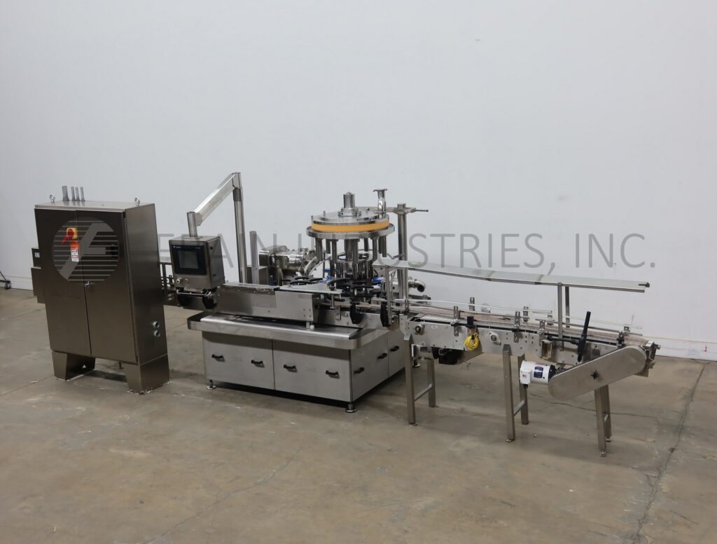
Pacific Packaging Machinery In Filler Liquid Pos Disp SL-7408-M-WB
- Manufacturer: Pacific Packaging Machinery In
- Model Number: SL-7408-M-WB
- Frain Number: R40340
Pacific Packaging, model SL-7408-M-WB, 8 head, inline, continuous motion, servo driven, mass flow meter filler. Rated up to 200 containers per minute – depending on materials, application and machine configuration. Container size range up to 4½” in diameter and 18″ in height. Equipped with a 4½” wide x 175″ long product conveyor with 33″ infeed and discharge height, 102″ long worm screw, (8) ½” diameter x 12″ long bottom up fill nozzles, (8) Endress + Hauser Dosimass coriolis mass flow meters, 42″ long nozzle bank on walking beam with 43″ of travel, reciprocating drip tray, 40 gallon product supply tank, SPX model 040-U1positive displacement pump powered by a 3 Hp drive, No bottle/No Fill, and Seko gauges. Control panel with AB PLC and touch screen HMI. Mounted on stainless steel frame with leveling feet and lexan guarding.
OAD: 178″ L x 81″ W x 94″ H
Get a Free Quote Call: 630-629-9900
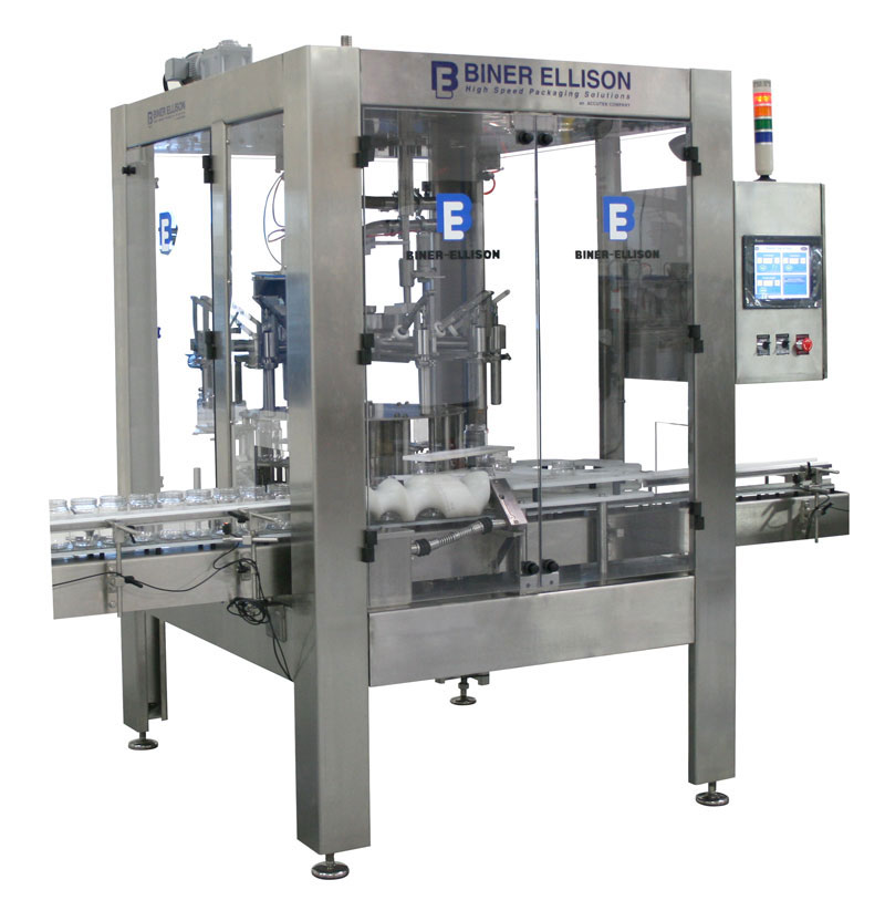
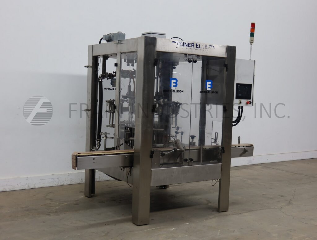
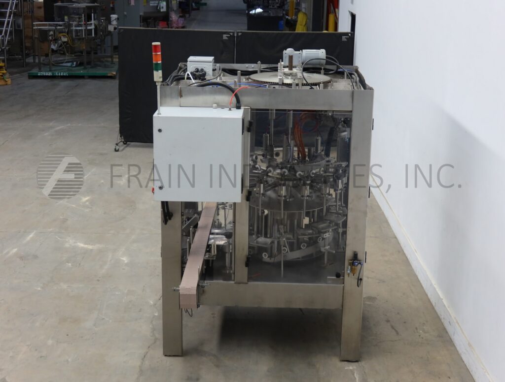
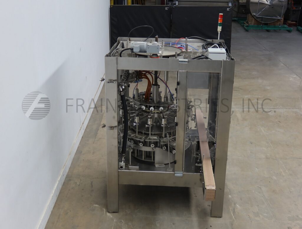
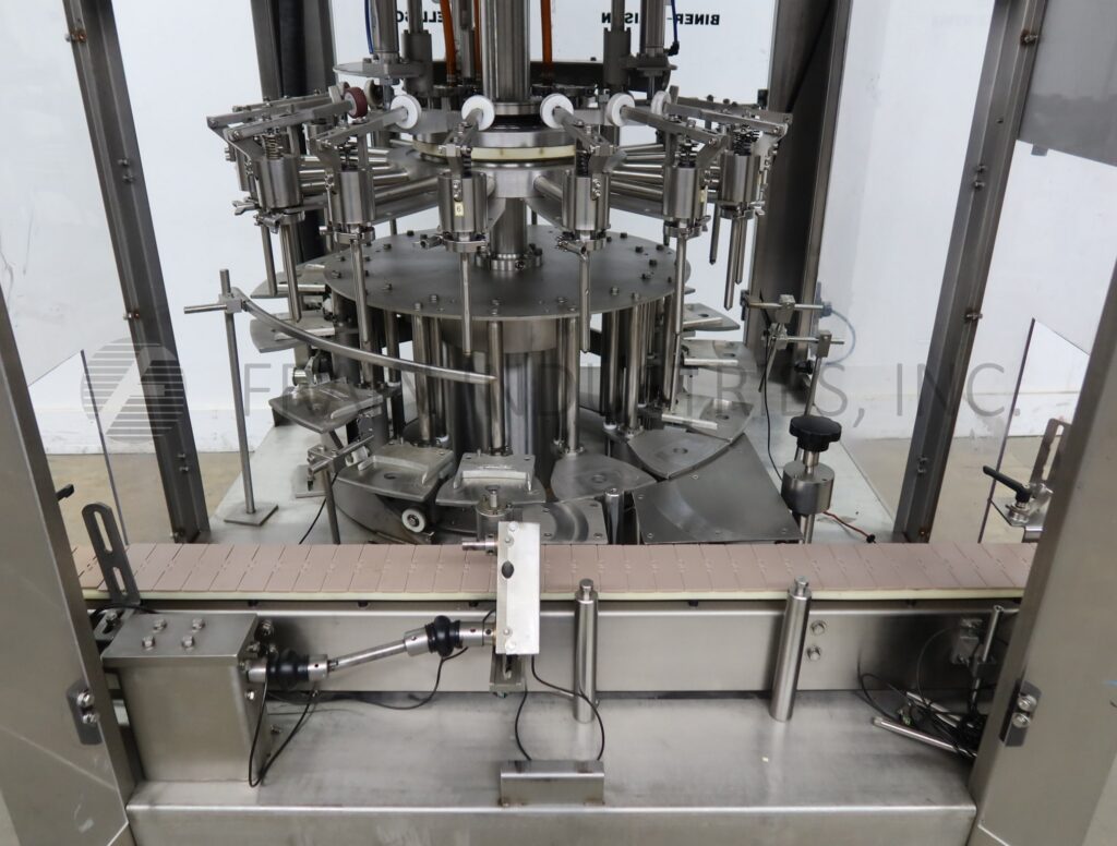
Biner Ellison High Speed Filler
- Manufacturer: Biner Ellison
- Model Number: 44-V40-016-BF
- Frain Number: R40170
Biner Ellison, Model 44-V40-016-BF, automatic, 16 head rotary, top driven, bottom up, time and flow pressure filler with number of containers per minute – depending on materials, application, and machine configuration. Container size: up to 6″ in diameter and 12″ in height with proper change parts. Equipped with wormscrew to star wheel indexing infeed and discharge, 4½” wide through conveyor, (16)(5/8″) OD positive cut-off stainless steel nozzles set on 7″ centers, 29″ OD turret. Control panel with touchscreen HMI. Mounted on heavy duty frame with safety guarding.
OAD: 109″ L x 61″ W x 92″ H
Get a Free Quote Call: 630-629-9900


Pacific Packaging Machinery In Filler Liquid Pos Disp V-16-B-22.000
- Manufacturer: Pacific Packaging Machinery In
- Model Number: V-16-B-22.000
- Frain Number: 5J6000
Pacific Packaging, model V-16-B-22.000, 16 head, 316 stainless steel, rotary, volumetric filler rated between 30 and 360 CPM – depending on materials, application and machine configuration. Fill size range: From 8 oz to 128 oz. Equipped with 96" long x 4½" wide through container conveyor with 24" long worm screw to star wheel indexing, SPX model 060U2 pump, bottom up filling and (16) 0.87" ID / 1.25" OD nozzles set on 4¼" centers. Control panel with A/B PLC controller and touch screen HMI controls on swing arm. Mounted on heavy duty stainless steel frame.
OAD: 96"L x 66"W x 102"H
Get a Free Quote Call: 630-629-9900


Pacific Packaging Machinery In Filler Liquid Pos Disp 10V00
- Manufacturer: Pacific Packaging Machinery In
- Model Number: 10V00
- Frain Number: 5J6001
Pacific Packaging, model 10V00, 10 head, 316 stainless steel, rotary, volumetric filler rated between 30 and 360 CPM – depending on materials, application and machine configuration. Fill size range: From 8 oz to 128 oz. Equipped with 184" x 4½" wide through container conveyor with 24" long worm screw to star wheel indexing, 16" diameter x 19½" straight wall product hopper, Waukesha model 130 pump, and (10) 0.87" ID positive cut off fill nozzles set on 8" centers. Control panel with A/B PLC controller and touch screen HMI controls on swing arm. Mounted on heavy duty 304 stainless steel frame.
OAD: 184"L x 68"W x 83"H
Get a Free Quote Call: 630-629-9900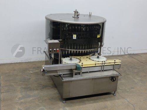


U S Bottlers Filler Liquid Grav/Press PGE-60
- Manufacturer: U S Bottlers
- Model Number: PGE-60
- Frain Number: 5J5920
US bottlers, model PGE-60, automatic, 60 head, stainless steel, rotary, gravity / overflow filler. Bottles per minute – depending on materials, application, size container and fill. Container size range: up to 3" in diameter, 4" to 12½" in height, capable of handling glass, plastic and metal containers with proper change parts. Equipped with 96" long x 4½" wide belt through conveyor, 36" long worm screw to star wheel indexing, 75" OD turret with 60 filling stations with ¾" OD nozzles set on 3¼" centers.
OAD: 109"L x 96"W x 95"H
Get a Free Quote Call: 630-629-9900


Pacific Packaging Machinery In Filler Liquid Pos Disp 6V04
- Manufacturer: Pacific Packaging Machinery In
- Model Number: 6V04
- Frain Number: 5J6003
Pacific Packaging, model 6V04, 6 head, 316 stainless steel, rotary, volumetric filler rated between 20 and 120 CPM – depending on materials, application and machine configuration. Fill size range: From 64 oz to 640 oz (5 gallons / 18.9 liters). Equipped with 24" long x 12" wide infeed roller, 12" long x 12" wide discharge roller, Infeed/discharge height of 28½" Waukesha model 130 pump, (6) 1½" ID / 1¾" OD open end nozzles set on 15¼" centers. Control panel with A/B PLC controller and touch screen HMI controls on swing arm. Mounted on heavy duty stainless steel frame.
OAD: 86"L x 54"W x 91"H
Get a Free Quote Call: 630-629-9900


Pacific Packaging Machinery In Filler Liquid Pos Disp 10V00
- Manufacturer: Pacific Packaging Machinery In
- Model Number: 10V00
- Frain Number: 5J6002
Pacific Packaging, model 10V00, 10 head, 316 stainless steel, rotary, volumetric filler rated between 30 and 360 CPM – depending on materials, application and machine configuration. Fill size range: From 8 oz to 128 oz. Equipped with 224" long x 4½" wide through container conveyor with 24" long worm screw to star wheel indexing, 16" diameter x 19½" straight wall product hopper, Waukesha model 130 pump, and (10) 1" ID bottom fill open end nozzles set on 8" centers, lane diverting discharge conveyor travels 12" on 4½" wide conveyor before being diverted to a 7½" wide conveyor for 56" before discharge with a discharge height of 39", flow-through pipeline metal detector. Control panel with A/B PLC controller and touch screen HMI controls on swing arm. Mounted on heavy duty 304 stainless steel frame.
OAD: 224"L x 68"W x 83"H
Get a Free Quote Call: 630-629-9900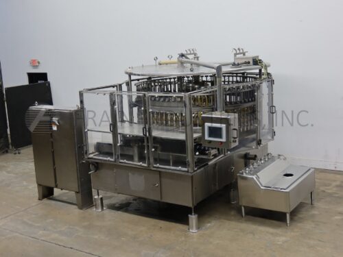


U S Bottlers Filler Liquid Grav/Press PG-72-96
- Manufacturer: U S Bottlers
- Model Number: PG-72-96
- Frain Number: 5J5520
US bottlers, model PG-72-96, automatic, 72 head, 304 stainless steel, rotary, gravity / overflow filler. Bottles per minute – depending on materials, application, size container and fill. Container size range: up to 4" in diameter, 4" to 12½" in height, capable of handling glass, plastic and metal containers with proper change parts. Equipped with 84" long x 3¼" wide stainless steel belt through conveyor, 34½" long worm screw to star wheel indexing, 100" OD turret with 72 filling stations with ½" OD nozzles set on 4¼" centers, 110-gallon product/overflow tank and touchscreen HMI on swing arm.
OAD (Filler): 179" L x 120" W x 99" H
OAD (Overflow tank): 51" L x 36" W x 36" H
OAD (Electric Cabinet): 50" L x 17" W x 78" H
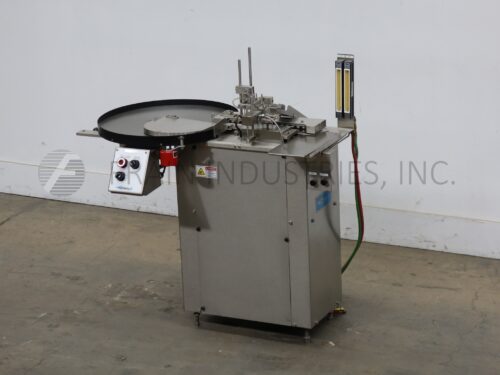
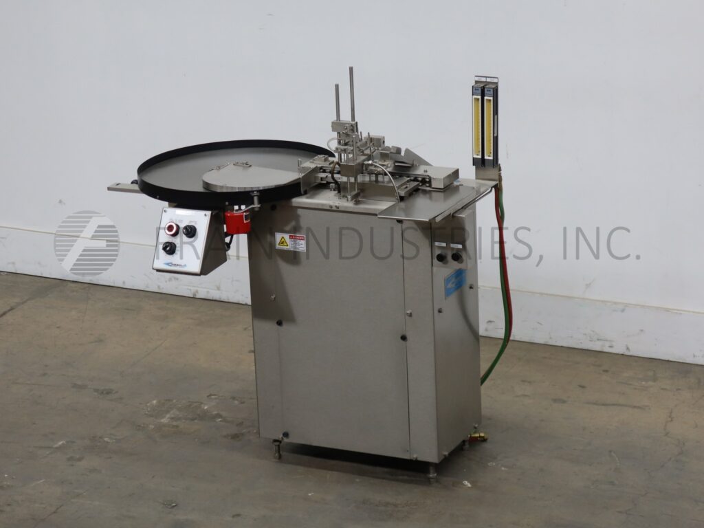


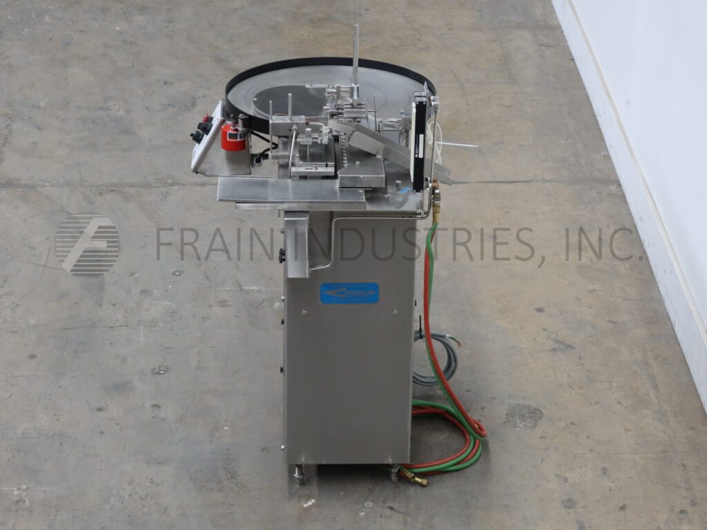

Cozzoli Filler Liquid Ampule FPS1
- Manufacturer: Cozzoli
- Model Number: FPS1
- Frain Number: 5J4790
Cozzoli, Model FPS1, Automatic, stainless steel, intermittent motion, 1-up, ampule unscrambler, flush, fill, flush and flame sealer rated from 15 to 60 ampules per minute – depending on materials and application. Fill range of .1ml to 33ml and volumes can be changed by adjustment of calibrated sector arm, accuracies of + / – 0.5%. Bottom-up filling. Container size range 3/8" to 1" OD has maximum container height of 5-5/16" with container sealing heights from 1¾" to 4¾". Fills one container at a time and capable of handling ampules, glass tubes, onion skin and vials (with proper change parts). Equipped with dual flow meter assembly that visually indicates the oxygen and gas flow separately and has 24" disc unscambler, fill piston, fill nozzle and flame sealer with pick off arms for ampule glass waste with ampule discharge chute. Control panel has vibrator on / off and cycle per minute switch with start, stop push buttons. Mounted on base frame with hight adjustable leveling legs.
OAD: 48"L x 30"W x 48"H
Get a Free Quote Call: 630-629-9900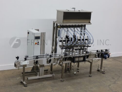


E Pak Filler Liquid Grav/Press 8 HEAD
- Manufacturer: E Pak
- Model Number: 8 HEAD
- Frain Number: R35300
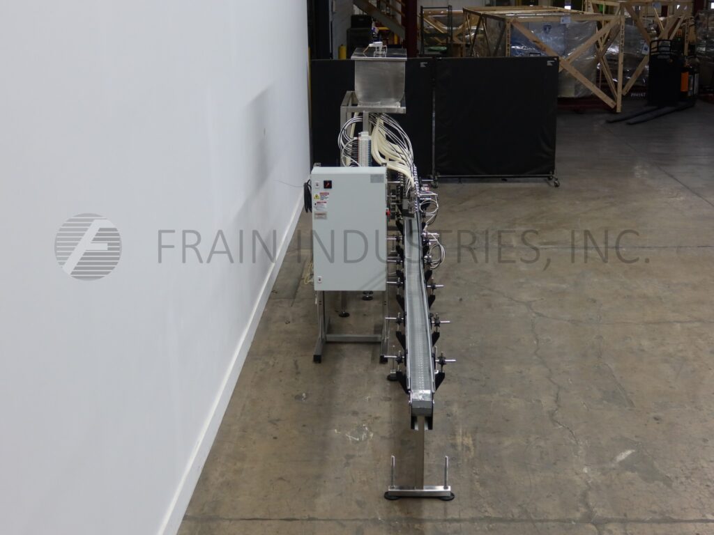
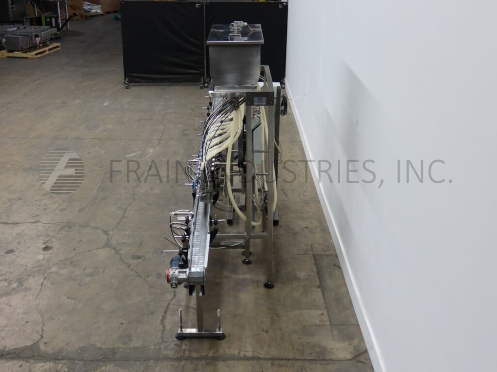
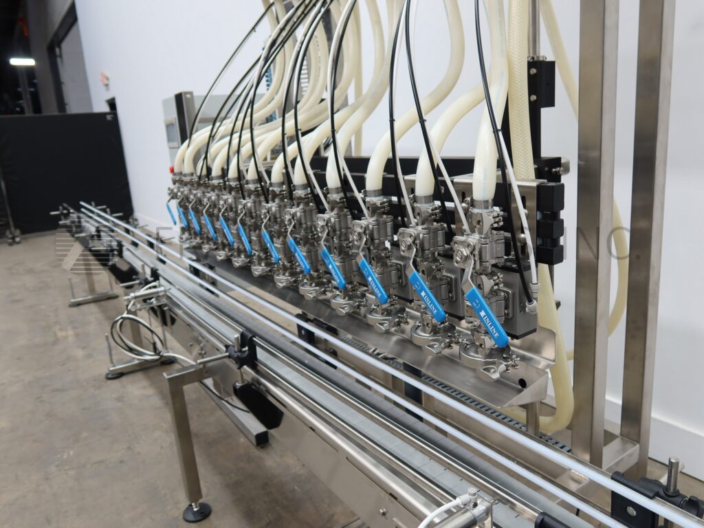
E Pak, Automatic, inline, 8-head, stainless steel, time-based gravity filler. Fill capacity from 1oz to 5 gallons with number of containers per minute – depending on materials, application and machine configuration. Equipped with 4½" wide x 144" long plastic delrin container conveyor, pneumatic container indexing, 48" long filling head slide bar has (8) (7/8)" OD positive cut off stainless steel diving nozzles with adjustable centers, 50" long drip tray and 45½" long x 17½" wide x 18" deep product tank. Control panel has touch screen operator interface with power / pump on / off and machine up / down switches. Mounted on stainless steel frame with casters and height adjustable locking legs.
OAD: 148"L x 38"W x 94"H
Get a Free Quote Call: 630-629-9900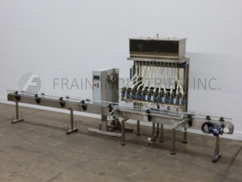


E Pak Filler Liquid Grav/Press 12 HEAD FILLER
- Manufacturer: E Pak
- Model Number: 12 HEAD FILLER
- Frain Number: R35110
E Pak, automatic, inline, 12-head, stainless steel, time-based gravity filler. Fill capacity from 1oz to 5 gallons with number of containers per minute – depending on materials, application and machine configuration. Equipped with 4½" wide x 235" long plastic delrin container conveyor, pneumatic container indexing, 58" long filling head slide bar has (12) 2½" OD stainless steel diving nozzles with adjustable centers, 60" long drip tray and 45½" long x 17½" wide x 18" deep product tank. Control panel has touch screen operator interface with power / pump on / off and machine up / down switches. Mounted on stainless steel frame with casters and height adjustable locking legs.
OAD: 240"L x 38"W x 96"H
Get a Free Quote Call: 630-629-9900
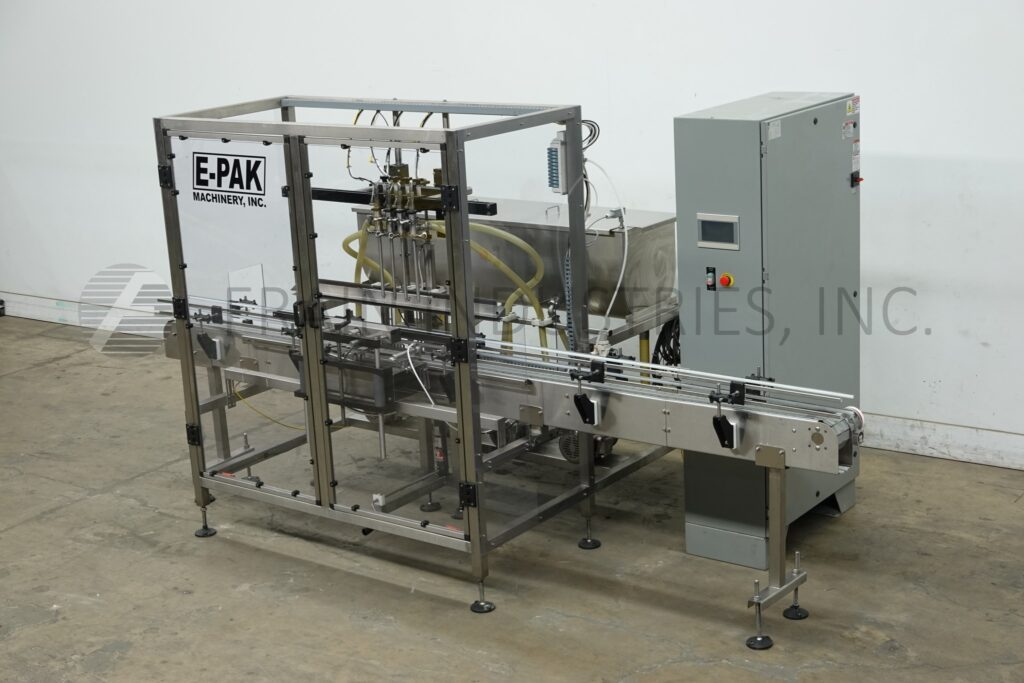
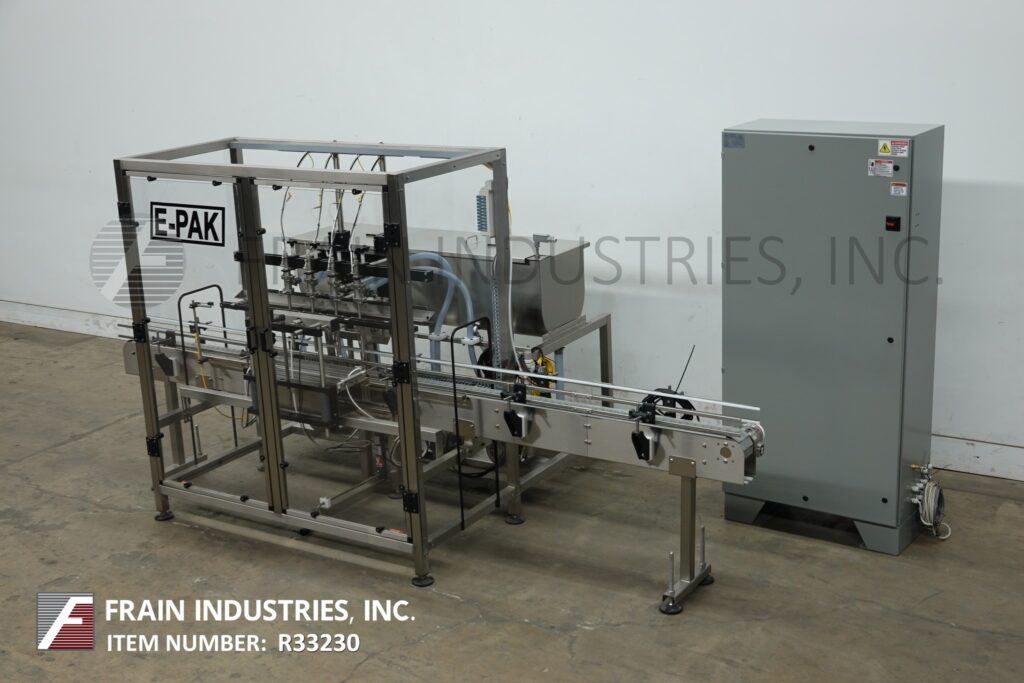
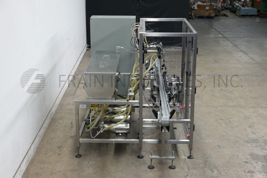

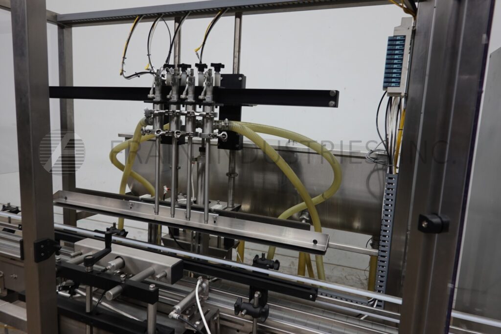
E Pak Filler Liquid Pos Disp 4HDGP
- Manufacturer: E Pak
- Model Number: 4HDGP
- Frain Number: R33230
E-Pak, 4 head, inline, stainless steel (316 contact, 304 non-contact) gear pump filler. Equipped with 149" long x 4.5" wide Delrin conveyor, bimba indexing system, four gear pumps, four 5/8" OD diving nozzles with positive cut off and product reservoir with float recovery system. safety guarding, A/B PLC with Panel View, NEMA 12 electrics with Ethernet port. Mounted on leveling legs. Rates dependent on materials, application and machine configuration.
OAD: 149" L x 75" W x 75" H Filler
36" L x 18" W x 75" H Control Panel