
LEARN MORE
VIDEOS
RELATED EQUIPMENT
LEARN MORE ABOUT
Capping, Overlidding, Induction Sealers & Tamper Evident Equipment
- Chucks and Clutches White Paper
- How to buy a Capper
- Cap Sorting White Paper
- Non-CTS Caps White Paper
- Solving Common Capper Problems
- Single Head Cappers
Chuck cappers can be rotary or inline, continuous or intermittent motion. They can run at speeds from 20ppm to 1200ppm or more. What all have in common is that the use a female chuck to engage the male cap and turn it down to a precise application torque.
The first thing to understand it that the end user is only interested in removal torque, sometimes called “off torque”. Too much removal torque and they will not be able to get the cap open. Too little and it will leak. Big leaks will make a mess, small leaks, even if no product escapes, may allow air to get in and spoil the product.
The goal on the packaging is to make sure that every bottle has the appropriate removal, sometimes called “off”, torque.
This is a problem. The capping machine can only control application torque or “on” torque. There is a relation between the two but it is not 1:1. An application torque of 10 inch-pounds might give a removal torque of 14 inch-pounds. Or, an on torque of 14 inch pounds may give an off torque of 10 inch pounds.
Capping machines have a lot of components but the two most key to consistent on and off torques are the chucks and clutches.
Chucks must grip the cap positively without slipping and the clutch must slip or release cleanly when the proper on torque is achieved.
Clutches are mechanical devices designed to slip or release when torque reaches the target setpoint. In this discussion, we will take a bit broader view and include other devices that are used to control the capper application torque.
Mechanical, friction or plate style clutches consist of 1 or more plates that are pushed together with springs. One plate is attached to the drive motor or shaft, the other to the chuck. Increasing the spring pressure increases the amount of friction between the plates and the torque before they begin slipping. A single pair of plates provides a relatively small surface area and requires considerable spring pressure for anything more than minimal torque. Most capping machines use clutches. These consist of an interleaved stack of metal and fiber plates. The fiber plates are connected to the chuck and the metal plates to the drive (or vice versa). The increased surface area requires less spring pressure and makes fine torque adjustment easier.
VIEW THE COMPLETE WHITE PAPER HERE: DOWNLOAD WHITE PAPER PDF
There are a number of machines, under the general heading of closing and capping that are used to seal containers on a packaging line. Some of these include Roll thread cappers, snap cappers, overlidders, can seamers, induction sealers and more. This article will focus strictly on screw cappers which screw the female thread of the cap over the male thread of the bottle. For brevity, this article will call them cappers.
There are hundreds of companies around the world which build or have built cappers. Some build one of a kind machines for a specific bottle/cap. Others build more general purpose machines that can be used with a wide variety of bottle/cap combinations. Each builder has their own designs but most can be broadly classified as chuck or disk styles.
Chuck cappers use a female chuck which comes down over the cap. The axis of the chuck is inline with the vertical axis of the bottle. Some chuck cappers use the chuck to pick up the cap and apply it to the bottle. Others apply the cap in a previous operation and use the chuck only for tightening.
Disk cappers use pairs of rotating rubber disks. These are arranged so that as the cap passes between their tangents make contact with the tangent of the cap causing it to rotate. Due to the limited contact surface and limited contact time, two to four pairs of disks are normally required for satisfactory tightening.
Both styles work well on a variety of cap and bottle combinations. Some bottle/cap combinations will run well on one style and not the other. In all cases selecting the proper capper is critical to the operation of your packaging line. A bit of extra time in the selection process will save many headaches in operation.
Here are some things to look for when buying a capper:
1. What style of cap do you have? Angled sides or a non-round shape may be difficult for the spinning wheels to get a grip on. For these a chuck may be the better way to go. Other caps such as a pump or trigger may not lend themselves to a chuck and the wheels will be the better choice.
2. Bottle rigidity – For some time bottles are getting lighter and lighter. This is a good thing overall but requires more care at the capper. Some chucks styles, particularly those with conical rubber inserts, can apply considerable downforce causing the bottle to collapse. If the bottle has a neck ring, it may be possible to use neck supports to absorb the downforce. The bottle must be gripped during capping to prevent spinning. Inline, disk cappers usually prevent this by the use of side belt grippers. It can sometimes be difficult to grip the bottle firmly enough to prevent spinning also without crushing it. If this is the case, a chuck capper which confines the bottle in a starwheel or grips it with circular clamps may be the answer.
3. Cross threading – Some cap/bottle combinations are more sensitive to cross threading than others. If a cap is not applied to the neck correctly, when it is screwed down the threads may not engage correctly leading to a cocked or cross-threaded cap. Needless to say, this results in an leaky cap. Disk cappers generally position the cap at an angle and let the bottle neck pull it out of the escapement. Guides push the cap so that it is flat on the neck before turning it down. Some caps may not work well in this type of application.
Chucks cappers generally use the chuck to position the cap so that it is applied vertically over the bottle neck. This greatly reduces cross-threading and may be essential with some cap designs.
4. Cap scuffing/shredding – Disk cappers use spinning rubber wheels to tighten the cap. Some chuck cappers use a shell with a rubber insert to tighten the cap. Both work well but it not properly adjusted, can slip. This can scuff the cap. It also generates rubber shreds. If the bottle is plastic, static will cause them to stick to the sides of the bottle. If a label is applied over these shreds, the label will be lumpy.
5. Workforce – All packaging machinery must be matched to the workforce.
6. Cap feeding – The feeding system orients the cap open side down and carries it to an escapement where it is applied to the bottle. Most feeder systems can run a range of flat cap sizes and styles. More complex caps, such as a flip cap or a spout cap, may require more specialized feeding systems. It is important to assure that any capper being considered have a feeder that can handle the desired cap at the desired rate of speed.
7. Torquing – The whole purpose of a capper is to tighten the cap. This is critical since if the cap is not tightened sufficiently, it can vibrate loose in shipment and leak. If too tight, the end user may have difficulty opening it. In extreme cases, overtightening can result in damage to the cap or bottle threads resulting in a leaky seal. Various types of mechanical or magnetic clutches, releasing chucks and servo motors may be used to provide correct application torque. The machine buyer must assure that the torque control is suitable for the application.
8. Lifespan/duty cycle – You get what you pay for and cappers are no different. When buying a capper, consider how it will be used and for how long. A plant running a single shift will be able to get by quite well with a much lighter duty machine than a plant running 24/7 at high speeds.
9. Changeover – Downtime due to changeover is important to any packaging line. Even small delays can be costly. Ten additional minutes per day, over the course of a year, will cost an entire week (40 hours) of plant capacity. If the line is going to run a single product and package, changeover is not an issue. The more products to be run, the more of an issue changeover becomes.
If a variety of sizes are to be run, spend a few extra dollars on a machine that is changeover friendly. This will minimize the amount of downtime.
Another changeover related factor is changeparts. The rotary chuck capper will require starwheels, guides, timing screws, chucks and perhaps other changeparts for each bottle size. If a new bottle is to be run, it may take 3-5
weeks to have the necessary parts fabricated. If there is uncertainty about what products are to be run in the future, an inline capper with few if any changeparts may be the better choice.
10. Speed/Capacity – Speed and capacity are related but not identical. When buying a capper or any other machine speed must be derived from capacity requirements. Figure out how many products per week (or month) you need to produce and how many hours you have to do it in. Subtract inefficiencies, , maintenance and other non-production time to get the time that you will actually be running. From this you will be able to derive the required speed. Be generous. It is cheaper to buy a little more capacity than you really need now than to replace the machine later.
11. Special features – Some products, such as hot filled foods and beverages, will need to inject steam into the bottle just before capping. Others may need to inject nitrogen or other gases. Still others will need to apply the cap in a vacuum. Some capper designs are more amenable to this than others. If there are special atmosphere requirements, they need to be identified early in the capper selection process.
The first step in capping is orienting the cap open side down. Cap feeders, sometimes called cap orienters or cap sorters are used to do this. They are typically mounted to the capping machine but can be standalone in some cases.
There are 6 common types of orienteers:
- Vibratory bowl feeder
- Centrifugal bowl feeder
- Elevating conveyor feeder
- Step feeder
- Vertical wheel
- Robotic feeder
In addition to the feeder itself, there is often a bulk supply hopper. Most feeders work best with a relatively small quantity of caps in the feeder itself. The bulk hopper is typically sized to hold 10-15 minutes or more of caps to minimize loading frequency. Many cappers mount the feeder above the capper. If an operator has to climb a ladder or steps to replenish the cap supply, there are safety and ergonomic risks. All cap loading should be done at floor level. This will require some type of cap elevator.
A common design is a hopper with a cleated conveyor. Caps are loaded and the caps conveyed up to the feeder. These are available in a variety of styles and sizes using belt or chain conveyor, and angles from abut 45 degrees to vertical.
Another option is pneumatic transport. Caps are dumped into the hopper and blown to the feeder by high velocity air. This may not be suitable for all caps, especially those with more delicate features.
In all cases, a sensor and controls are required in the feeder to closely maintain the level of caps for optimum operation. Do not rely on the operator. They already have enough to do.
TIP: Mark the inside of the hopper with red-yellow-green level strip. Red means that the hopper is low and more caps should be added immediately. Yellow means that caps should be added but it is not urgent. Green means that no caps should be added. The colors can be calibrated to reflect the number of caps in the hopper. This can be used to prevent excess caps in the hopper at the end of a production run.
VIEW COMPLETE WHITE PAPER: DOWNLOAD WHITE PAPER PDF
Continuous thread screw (CTS) caps are the most common cap type. They come in different sizes and styles. A number of different types of capping machines are available to apply them.
In general, closures can be grouped as caps or plugs. Caps are those closures which go over the bottle neck. Plugs are those which go inside. This whitepaper will cover non-CTS caps and their application.
ROPP
Roll On Pilfer Proof (ROPP) caps are sometimes called rolled thread caps. Roll-On because the threads are rolled into the cap during application. Pilfer proof because, on first use, the cap has obviously been opened. In non-skirted caps, the sealing ring remains on the neck providing clear visual evidence.
The customer sees little difference between ROPP and CTS caps. Functionally, they are very different. CTS caps rely on the cap and neck threads to pull the cap valve or pointer tightly against the bottle neck. As the cap is torqued down, the body of the cap and/or the bottle neck stretches slightly. If the cap is lined, there will also be some elasticity from the liner. This elasticity plus friction between threads is what keeps the cap sealed.
GET THE FULL WHITE PAPER: DOWNLOAD WHITE PAPER PDF
All packaging operations are important but capping is one of the most critical. An improperly capped bottle can leak product out or damage product by leaking air in. This paper will focus on continuous thread (CT) screw caps. It will walk you through some of the issues that arise and how to prevent or resolve them.
In any discussion of screw caps the key parameter is cap torque. On the packaging line there are two types of torque to be addressed: Application and removal torque. These are sometimes known as “on” and “off” torque. Application torque is a measure of how tightly the cap is screwed down. Removal torque is a measure of how much force is required to remove the cap. In virtually all applications, the removal torque drops to next to nothing once the cap has been loosened by 1/8th turn or less.
If there is too much application torque, the cap can be damaged, threads may strip or the end user may not be able to get it open. Too little and the cap may leak or may vibrate loose in shipping.
Application and removal torque are correlated but not are not necessarily equal. Ten inch-pounds of application torque may be required to provide 5 inch-pounds of removal torque for one cap/bottle combination. For another, ten inch-pounds of application torque may result in 15 pounds of removal torque. Once the relationship is established, a given application torque should consistently result in the same removal torque.
There are several machine and component related issues that can affect capping consistency. Before we get to them we need to discuss some other issues.
DOWNLOAD COMPLETE INFO SHEET: DOWNLOAD PDF
Single head cappers are standalone, inline, screw cappers with a single capping head or chuck. A common example is the Resina Model S-30.
Inline cappers using spinning wheels for tightening are common at speeds up to 200ppm or so. These are simple, effective and relatively low cost. They have 2 drawbacks:
If the cap tightening disks are not precisely adjusted, they can slip on the cap. When they do, torques will be inconsistent, the caps will be scuffed and the scuffing will generate rubber shreds which can get under the label making an unsightly appearance.
Disk cappers typically position the cap in an escapement, at an angle, and use the bottle to pull it out. Guides help transition the cap from the angle to flat. If not properly set, the cap will not be straight and cocked or cross-threaded caps will result. Some caps, especially those with a large diameter relative to the cap height, can be especially susceptible.

Chuck cappers avoid these problems by using the chuck to pick up the cap from a flat position and apply it squarely to the bottle. Bottle and cap are always parallel. The chuck grips the cap positively making it less likely to slip on the cap. This eliminates scuffing and particulates as well as torque issues caused by chuck slippage.
In a capper such as the Resina, the chuck spins continuously and reciprocates up and down. Caps are oriented and fed down a track to an angled escapement for pickoff. A horizontally reciprocating transfer arm picks the cap from the escapement and positions it under the chuck. The chuck dips down, grabs the cap and moves up.
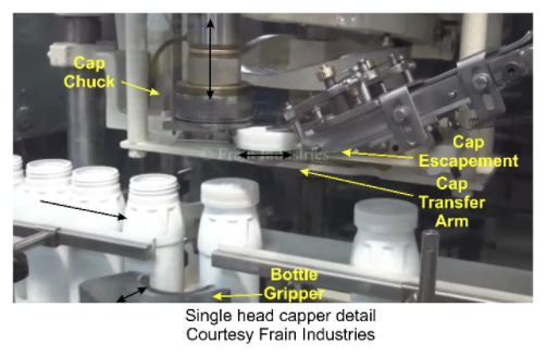
Meanwhile the bottle has been indexed into position and held in a gripper pocket to prevent turning as the cap is tightened. As the cap arm moves out of the way, the chuck lowers the cap onto the bottle and turns it down. A clutch breaks free when the correct application torque is achieved.
The main disadvantage of these cappers is speed, generally limited to a maximum of about 60ppm maximum depending on bottle and cap. On the plus side, they are generally fully mechanical except for the drive motor and an on/off switch. A single motor drives the machine and all major components operate off cams on the main shaft. This makes them very simple for any mechanic to maintain and makes them a good choice for plants and countries where technical skillsets are limited.
videos
Capping Overview
INLINE/QUILL CAPPER: SureKap Quill Capper Demonstration
ROTARY/CHUCK CAPPER:
ROTARY/CHUCK CAPPER: MRM & Pack West Liquid Filling Line Demonstration
INDUCTION SEALER: Pillar Capper Induction Sealer 2.25 KW Demonstration
NECK BANDER: Axon EZ200 Neck Bander And Heat Tunnel Demonstration
NECK BANDER: Axon Sleever / Neck Bander Demonstration
OVERLIDDER: E Pak Over-Lidder Demonstration
OVERLIDDER: Capper Overlidder Demonstrating Round Paperboard Containers
OVERLIDDER: Holmatic Automatic Inline Overlidder Demonstration
CAP TIGHTENER AND RETORQUER: NJM BELTORQUE Capper Demonstration
CAP TIGHTENER AND RETORQUER: Njm BELTORQUE Capper Demonstration
CAP TIGHTENER AND RETORQUER: SureKap SK600 Cap Retorquer Demonstration
RELATED EQUIPMENT


Capping, Overlidding, Induction Sealers & Tamper Evident Equipment MANUFACTURERS


